Design a Lifter using Solidworks App
Use the SolidWorks app to design and assemble a simple digital lifter with lever, pulley, and hook, learning 3D modeling and basic mechanics.


Step-by-step guide to design a lifter using SolidWorks app
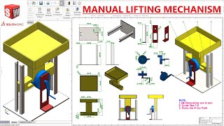
Mechanical Lifting Machine | Step-by-Step CAD Modeling in SolidWorks
Step 1
Open the SolidWorks app and start a new Part document.
Step 2
On the Front Plane start a sketch and draw a rectangle 120 mm by 20 mm for the lever.
Step 3
Extrude the rectangle 10 mm to create the lever solid.
Step 4
On the lever face start a sketch and draw an 8 mm diameter circle centered 10 mm from one short end.
Step 5
Use Extruded Cut through All to cut the 8 mm pivot hole in the lever.
Step 6
Start a new Part document for the pulley and hook.
Step 7
On the Front Plane start a sketch and draw a 30 mm diameter circle for the pulley disk.
Step 8
Extrude the pulley circle 8 mm to make the pulley disk.
Step 9
On the pulley face start a sketch and draw an 8 mm diameter circle at the center.
Step 10
Use Extruded Cut through All to create the pulley axle hole.
Step 11
On the pulley's outer face start a sketch and draw a J-shaped hook profile about 20 mm tall.
Step 12
Extrude the J-shaped sketch 4 mm to make the hook attached to the pulley.
Step 13
Start a new Assembly document.
Step 14
Insert the Lever part and the Pulley-with-Hook part into the Assembly and position them close together.
Step 15
Add a concentric mate between the lever pivot hole and the pulley center hole so the pulley can rotate on the lever and then share your finished lifter on DIY.org.
Help!?
What can we use if we don't have the SolidWorks app or it's hard to access?
If you don't have the SolidWorks app, use a free CAD alternative like Onshape or Fusion 360 and follow the same steps (Front Plane sketch, extrude the 120×20×10 mm lever, cut the 8 mm hole, create the 30 mm pulley and 8 mm axle hole, add the J-shaped hook, then assemble and apply the concentric mate).
The pulley won't rotate after I add the concentric mate—what should I check?
Check that both the lever pivot hole and the pulley center hole are modeled as 8 mm and that their axes are coincident on the assembly (align on the same plane) and that you haven't applied another mate that locks rotation or 'Lock rotation' is unchecked on the concentric mate.
How can I adapt this lifter design for different ages or skill levels?
For younger kids simplify by scaling the lever to larger, easier numbers (for example 60×30×10 mm) and using a premade pulley part, while older kids can add fillets, model an 8 mm pin through the pivot, and run a Motion Study to simulate the lever and pulley rotation.
How can we extend or personalize the finished lifter before sharing on DIY.org?
Extend the design by modeling and mating an 8 mm dowel pin through the lever pivot, adding a rope and a second pulley in the assembly to make a block-and-tackle, export parts to STL for 3D printing, and color the lever and J-hook for a personalized finish.
Watch videos on how to design a lifter using SolidWorks app
Lifting Conveyor Assembly and Motion Study Tutorial in Solidworks
4 Videos
Lifting Conveyor Assembly and Motion Study Tutorial in Solidworks
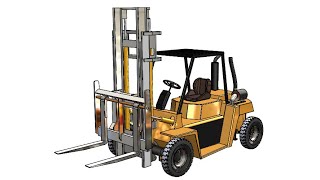
SolidWorks RE Tutorial #334 : Beginner Forklift complete video (Project 3)
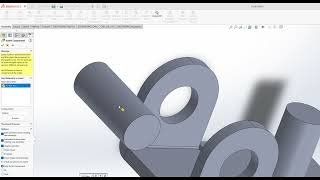
How to Make a Simple Lift Mechanism in SolidWorks | Step-by-Step Tutorial
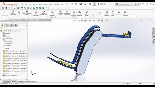
Design and Assembly Manual Lifting Mechanism in SolidWorks | Solidworks Tutorial
Facts about 3D modeling and basic mechanics
🖥️ SolidWorks was first released in 1995 and quickly became a top tool for designing 3D parts and assemblies.
🧩 3D modeling lets you spin, test, and fix parts on-screen before building them in real life—saving time and materials.
⚙️ One pulley can change the direction of a force, while using several pulleys together (a block and tackle) makes lifting much easier.
📏 A lever's mechanical advantage comes from arm lengths: a longer input arm makes lifting a heavy load simpler.
🧠 Learning CAD and 3D design boosts spatial thinking—it's like training your brain to solve 3D puzzles!
How do I guide my child to design a simple lifter in the SolidWorks app with a lever, pulley, and hook?
What materials, software, and tools do we need to design a digital lifter in SolidWorks?
What ages is designing a lifter in SolidWorks suitable for?
What are the benefits of designing a digital lifter in SolidWorks for kids?
