Build a 555 timer circuit
Build a simple 555 timer LED flasher on a breadboard using a 555 chip, resistors, capacitor, and battery to explore electronic timing and adjustments.

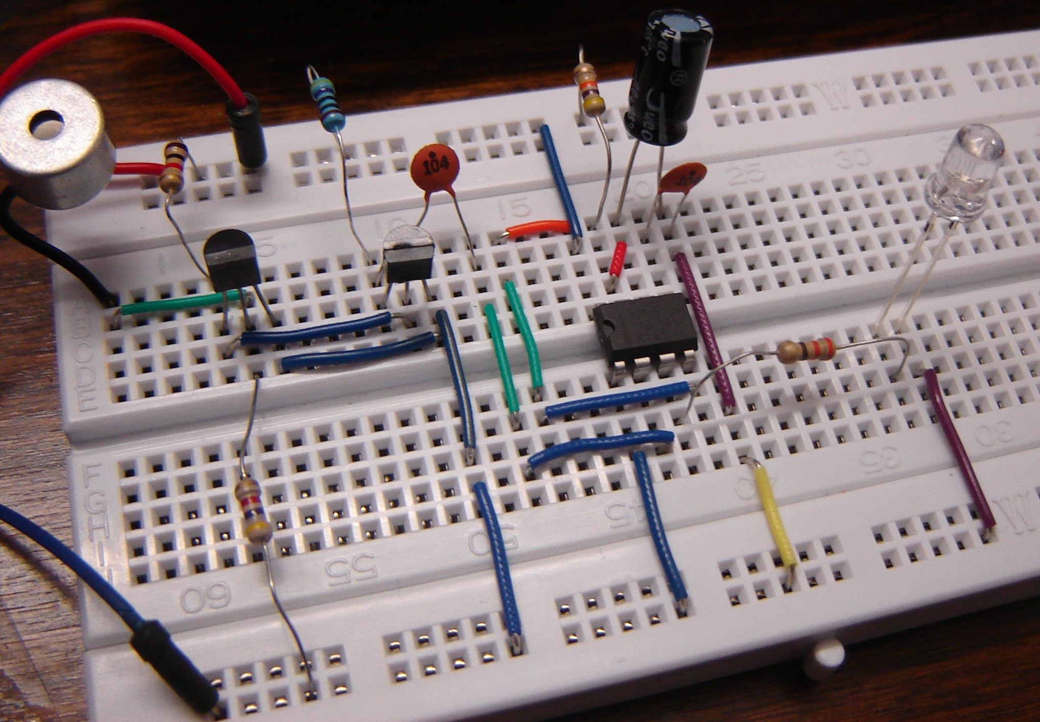

Step-by-step guide to build a 555 timer circuit
555 Timer IC (Basics, Features, Block Diagram, Pin Diagram & Working) Explained
Step 1
Find the notch or small dot on the 555 chip so you can tell where pin 1 is.
Step 2
Push the 555 chip into the breadboard so it straddles the center gap with the notch facing up.
Step 3
Clip the battery wires to the breadboard rails by putting the red wire on the positive rail and the black wire on the negative rail and leave the battery disconnected.
Step 4
Use a jumper wire to connect pin 1 (ground) of the 555 to the negative rail.
Step 5
Use a jumper wire to connect pin 8 (VCC) of the 555 to the positive rail.
Step 6
Use a jumper wire to connect pin 4 (RESET) of the 555 to the positive rail.
Step 7
Use a jumper wire to connect pin 2 and pin 6 together on the breadboard.
Step 8
Place the 10 µF electrolytic capacitor between the pin 2/6 junction and the negative rail with the capacitor’s negative leg to the negative rail.
Step 9
Put the 10 kΩ resistor between the positive rail and pin 7 of the 555.
Step 10
Wire the 100 kΩ potentiometer so one outer leg goes to pin 7 and the middle wiper leg goes to the pin 2/6 junction.
Step 11
Place the 220 Ω resistor from pin 3 (output) to an empty breadboard row.
Step 12
Insert the LED so its long leg (anode) goes into the same row as the resistor and its short leg (cathode) goes to the negative rail.
Step 13
Ask an adult to help you connect the 9 V battery to the clip to power the circuit.
Step 14
Turn the potentiometer knob slowly and watch the LED blink faster or slower as you adjust the timing.
Step 15
Share your finished blinking LED 555 timer circuit on DIY.org.
Help!?
What can we use if we can't find the 100 kΩ potentiometer, the 10 µF electrolytic capacitor, or a 9 V battery?
You can substitute the 100 kΩ potentiometer with a fixed 100 kΩ resistor or a smaller-value pot in series wired between pin 7 and the pin 2/6 junction, use two 4.7 µF electrolytic capacitors in parallel (with their negative legs to the negative rail) in place of the 10 µF, and power the breadboard by connecting a 9 V DC adapter or a 6×AA battery pack to the rails instead of the 9 V battery clip.
The LED doesn't blink — what should I check first?
If the LED doesn't blink, re-seat the 555 so the notch faces up and the chip straddles the breadboard gap, confirm pins 2 and 6 are tied together and the 10 µF capacitor's negative leg goes to the negative rail at that junction, make sure the LED's long leg is in the same row as the 220 Ω resistor and its short leg goes to the negative rail, and verify the battery clip is attached to the correct rails and the battery is connected.
How can this activity be adapted for different ages?
For ages 5–7 have an adult pre-insert the 555, capacitor, and resistors and let the child plug in the LED and turn the potentiometer knob, for ages 8–12 let them assemble all jumper wires and place the electrolytic capacitor with supervision, and for teens challenge them to change the 10 kΩ/220 Ω resistor values or replace the 100 kΩ pot to explore how the blink timing from pin 3 changes.
How can we extend or personalize the blinking LED project after it works?
To extend the circuit, swap the 100 kΩ potentiometer wiring for a photoresistor (LDR) between pin 7 and the pin 2/6 junction to make blink speed respond to light, add a second LED with its own 220 Ω resistor to pin 3 for dual-color effects, or mount the assembled breadboard into a small project box and label the potentiometer before sharing on DIY.org.
Watch videos on how to build a 555 timer LED flasher
How 555 timers Work - The Learning Circuit
4 Videos
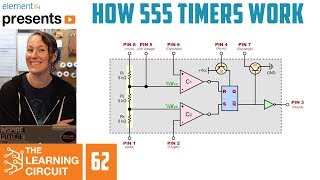
How 555 timers Work - The Learning Circuit

Introduction to 555 Timer: The Internal Block Diagram and the Pin Diagram Explained
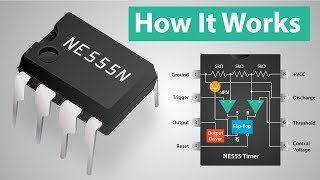
How a 555 Timer IC Works
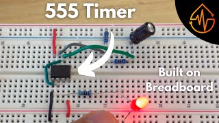
555 Timer | Build on Breadboard
Facts about electronics and timing circuits
🧪 The 555 timer IC was invented by Hans Camenzind in 1971 and is one of the most-produced integrated circuits ever.
🔁 Put a 555 in astable mode and it will blink an LED — changing the resistor or capacitor can make the flash go from milliseconds to minutes.
💡 A 555 can drive a small LED directly (with a current-limiting resistor), but larger loads usually need a transistor or driver.
🛠️ Solderless breadboards let you swap components instantly, so you can try lots of resistor/capacitor combos without soldering.
🎛️ The blink speed in a 555 astable circuit scales with the resistor×capacitor value (R×C), so doubling the capacitor roughly doubles the period.
How do I build a simple 555 timer LED flasher on a breadboard?
What materials do I need to build a 555 LED flasher?
What ages is building a 555 timer flasher suitable for?
What are the benefits, safety tips, and variations for this 555 timer activity?
